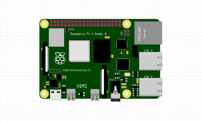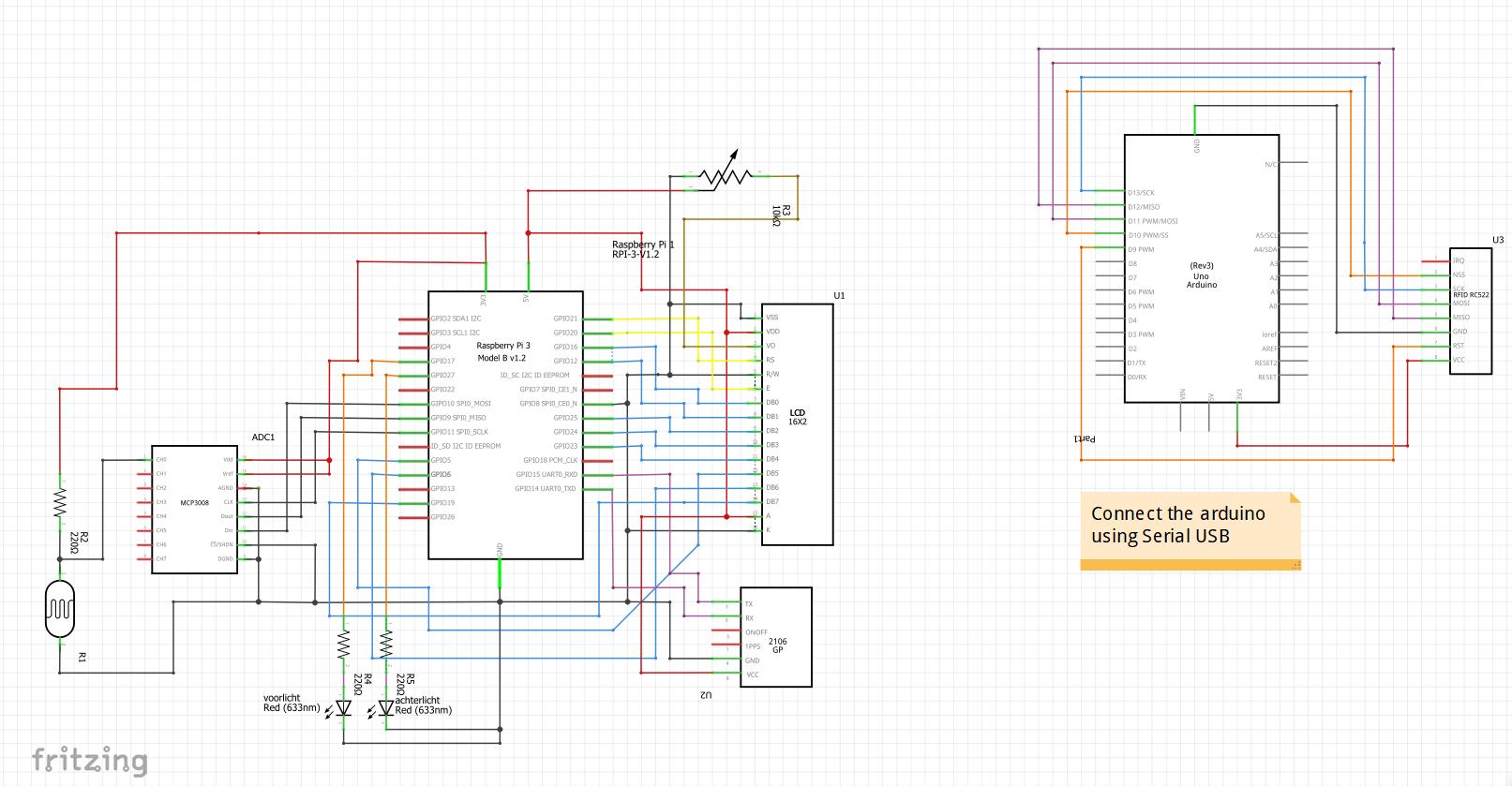

įritzing, which had been in beta since its beginning, had undergone significant development by 2011. With a view toward minimizing the software’s overhead, they chose to avoid using gradients wherever possible. While the “PCB” and “schematic” asset designs are fairly structured, the “breadboard” part’s design allowed me to rework 2D features that are typically found in 3D. This sets the stage for the production of three SVG elements, representing the PCB, schematic, and breadboard views, which will afterward get connected with one another. To begin designing an electronic component for Fritzing, they reviewed the relevant datasheet to familiarize me with the possible connector types. Instructions for making an electronic device. ESP-C3-32S support low-power Bluetooth:Bluetooth5,Bluetooth mesh. Bluetooth rate support:125Kbps,500Kbps,1Mbps,2Mbps. Support broadcast extension, multi-broadcasting, channel selection.Request PCB Manufacturing & Assembly Quote Now


The perfect security mechanism enables the chip to be perfectly applied to various encryption products. ESP-C3-32S has a variety of unique hardware safety mechanisms.The hardware encryption accelerator supports AES,SHA and RSA algorithm. Among them,RNG,HMAC and Digital Signature module provide more security features.Other security features include flash encryption and se-cure boot signature verification, etc. ESP-C3-32S module provides a wealth of peripheral interfaces, including UART,PWM,SPI,I2S,I2C,ADC, temperature sensor and there are 21 GPIOs. This module core processor ESP32-C3 is a Wi-Fi+ BLE combination of system-level chips (SoC), designed for various applications such as internet of things (IoT), mobile devices, wearable electronics, smart home, etc. You would then connect the signal pin from your Arduino to one of the signal pins on this module (for example, pin “HV1”), and then you would connect the desired signal pin on the module to the corresponding pin on this module (“LV1” if the higher voltage signal is connected to “HV1”).ĮSP-C3-32S is a Wi-Fi module developed by Ai-Thinker. Then, you would connnect the “LV” pin on the module to the 3.3V power source that is supplying power to the module and connect the “GND” pin near the “LV” pin to the 3.3V power supply’s ground. For example, if you were connecting your Arduino (5V signals) to a module (3.3V signals), you would connect the “HV” pin on the module to the 5V supply pin on your Arduino and the “GND” pin near the “HV” pin to the “GND” pin on your Arduino. Also connect the lower voltage source to pin “LV” and its ground to pin “GND” near the “LV” pin. Connect the higher voltage source to pin “HV” and its ground to pin “GND” near the “HV” pin. This module requires you to supply it with power from both the higher voltage level and the lower voltage level.


 0 kommentar(er)
